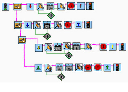
Project 1
Ramp Robot: Prototype I
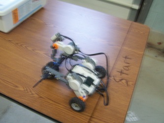
My first design was merely based off of the Basic NXT tutorial, at least the back tires. For the front, I decided to put two wheels on one motor to add more power. I then made a simple program that made motors A, B, and C forward. I soon figured out that the front wheels, motor B, needed to move in reverse because it was facing the opposite way of the other motors. After fixing this small problem I was able to make the robot move up the ramp, but at a low angle. When I moved up the ramp the robot just flip over indicating that there is to much weight on the back. I was going to add more weight to the front, but after thinking how I'm going to make the robot move straight up I came up with a different design.
Ramp Robot: Prototype II
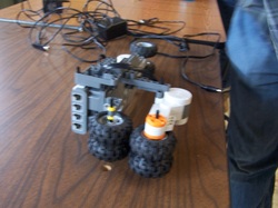
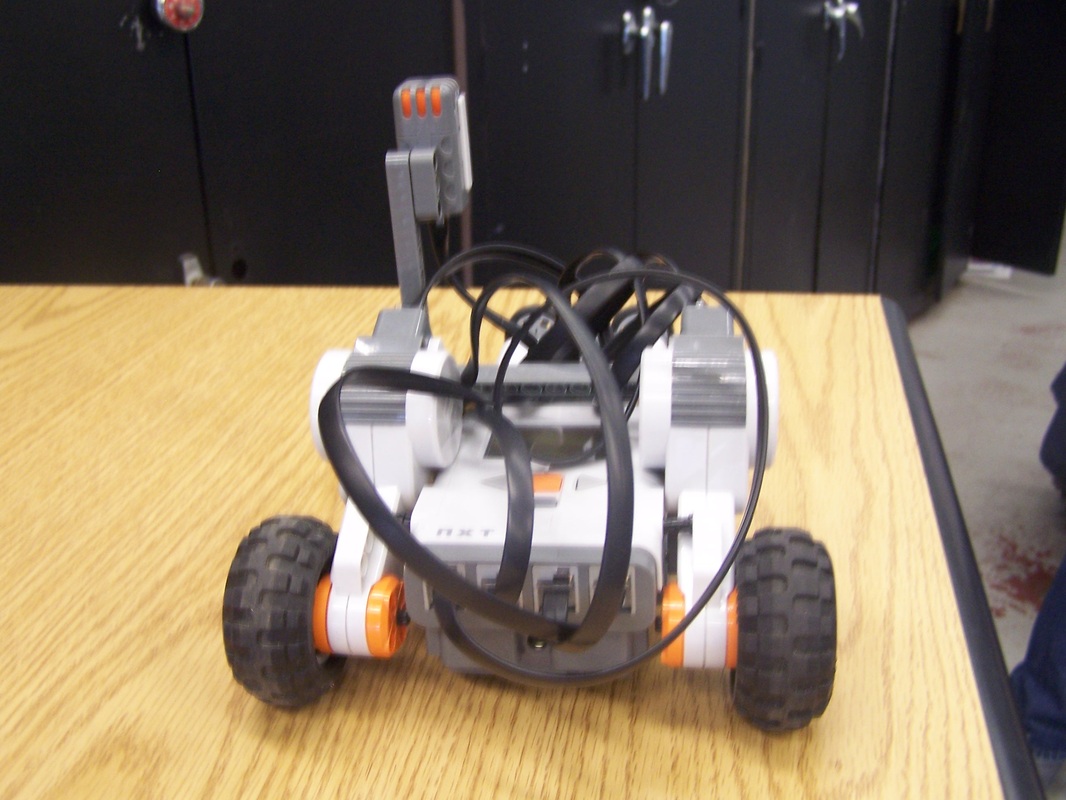
With this design, I wanted to use both sides of the boards so the robot could move straight up. Looking back at my first prototype, I put two wheels on one motor for the back end. I then focused on creating a wheel that would go under the wood. I actually got some ideas from pictures I have seen from other people's robots. I knew what I was going to do, but I just needed to figure out how to make it. I seen in the photo, I connected the motor to the side of the NXT and added more pieces to make it less flimsy. I then connected a wheel to the front of the robot so it would go above that wheel under the board. I created the program to move forward up the ramp and it did well when it was at a smaller angle, but it just couldn't handle going up the steep ramp.
Ramp Robot: Prototype III
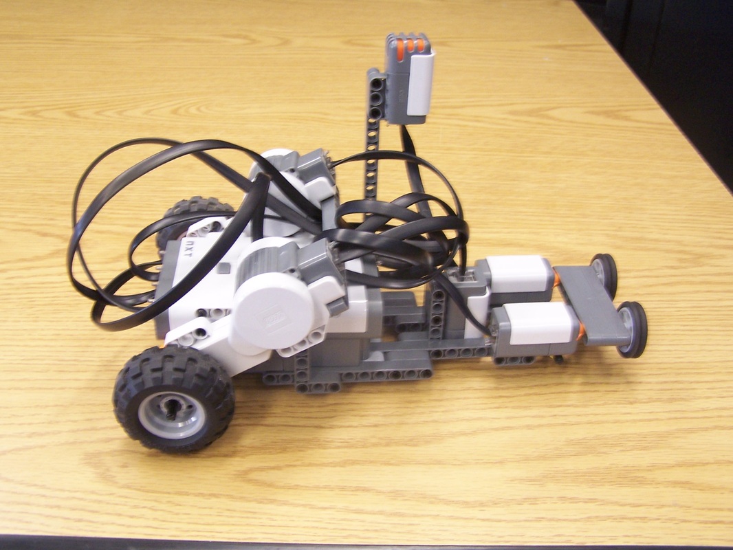
For my last design, I did not change much from my second prototype. The wheel on the bottom front and the wheel on the top front have been given a second wheel to add more power. All of the motors on my NXT have two wheels on them as I figured they would make the robot move up the ramp at a steeper angle and be more powerful. I tried it out on the ramp and by making a few minor adjustments I was able to make the robot go up at the highest point, but not completely vertical. The video below will show how effective my robot was as it went up the ramp.
| 100_5422.mov |
Ramp Robot Video
Project 2
Light Sensor Robot
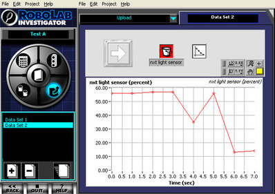
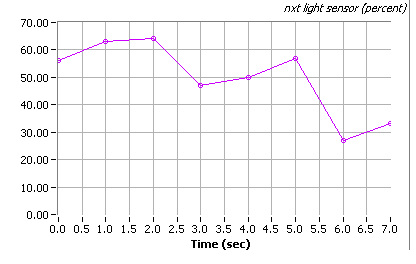
This is the data I collected from my light sensor robot. The graph on the left shows the amount of time the light sensor sensor was active and when, in the process, it went over the black tape. The Y-axis tells me the percentage of light that was there at the time and the X-axis shows me when and how long the increase or decrease of the light there was. As seen in the graph, the amount of light when my robot started was about 55%. After four seconds, the light decreased to 35% as it went over the black tape. The light then increased at five seconds as it went in the area between the black tape. The graph can also tell me the speed that my robot was going. Each piece of tape is two feet apart, my robot took three seconds to go between each tape to the other. In conclusion, my robot was going 2/3 foot per second.
Touch Sensor
Even though I am Level 2, I still wanted to make a touch sensor robot. I first came up with an idea to put the touch sensor near the wheels in front of the robot, the touch sensor would then get pushed every time the wheels made a full rotation. But this modification interfered with the motion of my robot, so I had to come up with a different technique. I received help from Mr. Croke in making a program that made a motor, that was attached to the touch sensor, rotate back and forth when the A and C motors made two full rotations. I attached the motor and touch sensor to the NXT and built something that, when the sensor was pushed down, the button would be pushed against to collect data. Unfortunately, with technical problems and the interest of time, I was not able to produce a data log for the touch sensor.
Touch Sensor Video
Click to set custom HTML
Project 3
Prototype 1
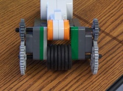
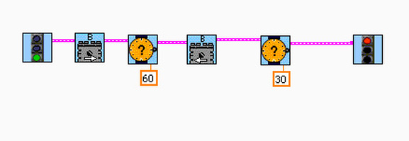
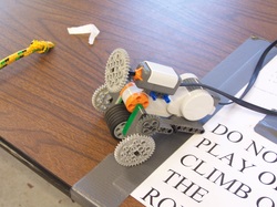
This is the first prototype of my rope climb robot. Step one was to figure out how I was going to get the robot to attach to the rope. I decided to wedge the rope between the actual motor and wheels to give it more of a grip. I went through several wheels, figuring out which one's worked well, and I went with these thin wheels seen on the right. I put the wheels as close as I could to the motor in order to cause a better grip, but didn't put them too close so the rope could fit through. I thought about adding a second motor to turn the wheels, but then I decided to put on gears. This way I could have both the motor and the second pair of wheels rotating at the same speed and time. It was also an advantage because it drastically reduced the weight. I installed the program seen below to make the motors rotate forward for 60 seconds in order to go up the rope and then reversed the motor for 30 seconds, considering that gravity will take part in bringing it back down. The robot was successful, with a few minor problems such as messing up on the program and making the robot go up, but not come back down. It was an easy mistake to fix. But I felt that I could have improved the robot so I came up with prototype 2
Program 1
Prototype 2
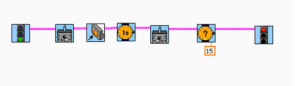
This prototype isn't that different from the first except for the addition of a touch sensor. With this touch sensor I wanted to make the robot climb up the rope and then, when the touch sensor was pushed down by the pole the rope was hanging on, it would come back down without having to rely out a certain amount of time. The program seen below shows that motor A will rotate forward until the touch sensor is pressed in which, after a one second delay, motor A will go in reverse for 15 seconds and stop. This was the final prototype and was successful after a few attempts. The video below shows the robot steadily climbing the rope and then coming back down.
Program 2
Rope Climb
| rope_climb.wmv |
Project 4
Roach Bot - Scared of Light
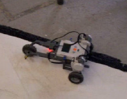
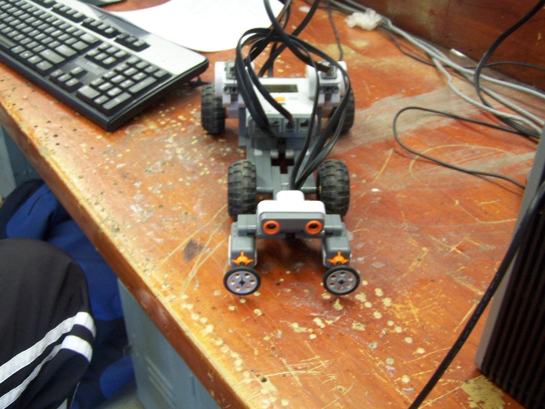
This is the roach bot that my partner and I created. The primary goal of this robot was to move slowly and randomly throughout the white circle while the lights are off. After, when the lights are turned on, the robot flees quickly in a straight line. This is suppose to resemble the actions of a cock roach. I first started by creating a simple bot with two motors and two wheels in the back and then a free moving wheel in front as seen in the picture to the right. The light sensor facing upward in the middle detects the light in the room and by using the program below we told it to commence the slow random motion when the light was below 33. When the light sensor detected light higher than 33, the program would go out of the loop and move motor A and C forward quickly.
Roach Bot - Path Follower
This roach bot is designed to follow the path on the floor while staying in the white part of the path. We kept the same structure as the first prototype except we flipped the light sensor so that it faces the ground. This lets the sensor detect the amount of light on the ground. The white paint is obviously lighter than the dark paint, this differentiates which path we want the robot to follow. When using the program below, the light sensor will detect the amount of light below and above 40. When the light is lower than 40, motor C will move and stop motor A. When the light is higher than 40, motor A will move and stop motor C. This will make the robot move from side to side slightly, but will allow it to follow the path because the light sensor will stay where it is most dark: the black line. Our roach bot was successful in following the path and can be seen in the video below.
RoachBot 1
RoachBot 2
| 100_6278.mov |
| 100_6277.mov |
Project 5
Escape Bot
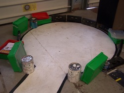
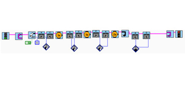
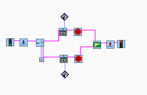
This "Escape Bot" is designed to get out of this circle in which there is only way out. It uses a sonic sensor as well as two touch sensors to move about the circle and get out through the space. The sonic sensor works by sending out sound waves and receiving them back. If the sonic sensor receives the sound waves faster than the set length, such as twenty centimeters, it will ensue the program that it is told to do. Our sonic sensor is set to twenty centimeters, the program will then tell the bot to back up and turn 90 degrees when the sensor detects an object less than twenty centimeters away. The touch sensors are used as a back up. If the sonic sensor does not detect an object, the touch sensors will bump into that object and then commence the program by backing up and turning ninety degrees left or right depending on which touch sensor is pushed. Eventually, the bot will find it's way out through a number of manuevers. Being in level 2, the bot had to get out of the circle in less than ninety seconds. Our bot got out in less than thirty seconds as seen in the video shown below.
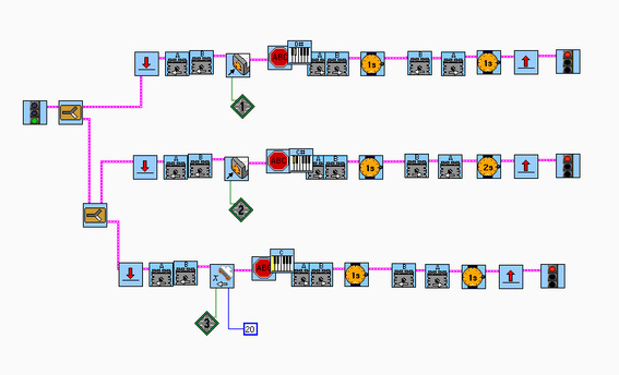
The program I created below is divided into three basic programs. By using task split, the program uses two touch sensors and a sonic sensor to perform three different programs. When the first touch sensor is pushed, motors A and B will reverse and then B will go forward and A will go backwards, and vice versa for the second motor. The sonic sensor has a similar movement except it makes smaller turns so it does not over shoot the gap in the hall. The jumps that are seen before and after the programs tell the program to go back to the beginning and restart. I was impressed by this robot because it uses a sort of artificial intelligence to make desicions on its own.
The program I created below is divided into three basic programs. By using task split, the program uses two touch sensors and a sonic sensor to perform three different programs. When the first touch sensor is pushed, motors A and B will reverse and then B will go forward and A will go backwards, and vice versa for the second motor. The sonic sensor has a similar movement except it makes smaller turns so it does not over shoot the gap in the hall. The jumps that are seen before and after the programs tell the program to go back to the beginning and restart. I was impressed by this robot because it uses a sort of artificial intelligence to make desicions on its own.
Reflection Guide
The assignment was to build and program a robot that could escape out of a circle blocked by certain objects. Using a sonic sensor and touch sensor you must leave the circle through the small space provided to be successful.
Having used the touch sensor in previous projects I already understood how it worked and what it can be used for, but the sonic sensor was something that I was unfamiliar with. In order to understand how the sonic sensor works I went to the “Help” option in Robolab. There I read how the sonic sensor works and what it can be used for. I also received assistance from Mr. Croke on how to create multiple tasks in one program, an essential part of this assignment.
We first built a basic robot with two motors that could simply move forward. After building the robot we focused more on the program and exactly how we were going to use both the sonic and touch sensors on our robot. We quickly created a touch sensor program because we have had past experience with it. We then worked on the sonic sensor program. After learning more about this sensor we adjusted the distance the touch sensor would detect an object and created a task for the robot to perform when the distance was less than the value we gave it. After multiple tests and retakes, we successfully got out of the blocked circle in less than half a minute and recorded a video of it.
The robot we built is designed to maneuver around objects. With the sonic sensor attached it acts as if it had artificial intelligence, making decisions based on its surroundings. Without the sensors it is just a basic robot that can only move forward, but with the sensors attached it can, eventually, make its way out of any obstacle in its path.
I received feedback from peers telling me that the robot could move a lot more efficiently if I changed the program slightly. Taking this advice I changed the amount of time the robot would back up and turn, this made the bot turn better and saved me a lot of time to get out of the circle.
I learned much from this assignment, but the thing I learned about the most was the advantages of a sonic sensor. The sonic sensor is an amazing tool that I will most definitely use in future projects. This sensor was extremely helpful and impressed me on how smart these robots can actually be. I also learned how to create more complex programs that I would have never been able to do in the past. I learned to split programs into multiple tasks giving it various aspects that will change my outlook on programming these bots.
If I could do this project all over again I would change the program that I created. The rotation of the robot depends entirely on the amount of time the motors would turn. For example, I had one motor go forward for two seconds and the other motor rotate the other direction for two seconds. I would have rather set the amount of rotation the motors turn than use a time limit, but with all the problems we had fixing and figuring out how program will work, we felt it was an unecessary to switch to number of rotations.
Escape Bot Video
| 100_6537.mov |
Complete Kit: Term 3
Project 6
Scan Robot
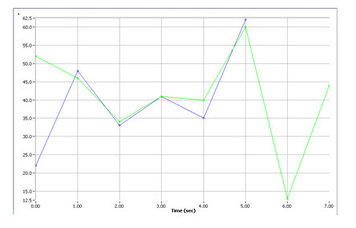
The purpose of the scan bot is to have the light sensor scan a letter on a white sheet of paper and we must determine what letter the bot scanned just by looking at the graph it produced. This graph to the left represents the number "3" that was scanned by our robot. The blue line represents the "3" we scanned for our first test. The green line is the "3" that Mr. Croke scanned for us to guess what number or letter he scanned. We had to compare our previous graphs to the graph that Mr. Croke produced for us. We already knew that it wasn't an "N" or a large "M". But we had to decide whether it was a small "M" or a "3". We thought it was the "M", but it ended up to be a "3" that Mr. Croke scanned. The comparison graph to the left clearly shows the similarities between each graph.
Reflection Guide
The assignment was to build and program a robot that scans a black letter on a white sheet of paper using the light sensor. Without looking at the robot scan the letter and using the graph produced, we had to figure out which letter was scanned.
I already knew how the light sensor worked and what I can do with it. So I already had a basic idea of how the robot was going to be built. What we needed to figure out first is how the letters would appear on a graph after being scanned by the light sensor. We scanned four different letters and numbers; a large M, the number 3, the letter N, and a small M. Now that we know what the letters look like on a graph, we compare these to the final scan in which we have no idea which one was scanned.
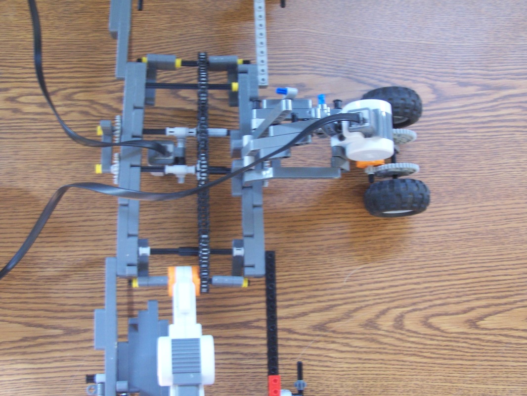
We first brainstormed several ideas on how the robot was going to scan the letter. Our first idea was to use gears and put them on a track to move back and forth. Out second idea was to make a robot that slides between to slots and use a pully system that pulls the sensor across. We ended up combining these two prototypes and built a robot that slides through the slots, but moves by using gears and a chain. The gears are attached to the light sensor and ride along the chain making the light sensor move with it. We then scanned several letters and produced four graphs to compare to the final scan that we will be given.
We received the graph that Mr. Croke produced when he scanned the letter with our robot. Looking back at our previous scans, we compared those graphs to the final one. We eliminated a few graphs that were not at all similar to the graph we had to interpret. We then decided that the graph Mr. Croke scanned was a small "M". We were wrong, after looking back at the graphs, we now clearly see that the graph was the number "3"
There was a significant amount of feedback we recieved. One student suggested that if we keep only one side of the chain on the gears then it would move much smoother. So what we did was have one set of gears lifting up the top of the chain and lay the gears that are attached to the light sensor on the bottom chain. This was extremely beneficial and made the robot move a lot faster and smoother. Another student suggested that we have wheels far out from the center of the bot, so the paper could move freely and not touch any part of the bot. Overall the feedback was extremely helpful and it was good to hear positive comments from my peers.
I learned that gears don't just have to be used on motors to makes wheels faster or stronger. But they can be used to move various parts of the robot itself. With the chain being a major asset to our project, we were able to use the gears in a way we have never thought of. I also learned about the use of comapring graphs. In Robolab Investigator, there is an option you can choose that puts to graphs on each other to get a close examination of the graphs and their similarities.
If I were to do this project again I would use the graph comparison option in Robolab Investigator. When comparing the final graph to the test graphs we only looked at similarities the graphs had, but we did not use the graph comparison. I would also have made a more stable and convenient robot. Our robot does the job right, but it was frustrating to make small changes and add and remove pieces.
I already knew how the light sensor worked and what I can do with it. So I already had a basic idea of how the robot was going to be built. What we needed to figure out first is how the letters would appear on a graph after being scanned by the light sensor. We scanned four different letters and numbers; a large M, the number 3, the letter N, and a small M. Now that we know what the letters look like on a graph, we compare these to the final scan in which we have no idea which one was scanned.
We first brainstormed several ideas on how the robot was going to scan the letter. Our first idea was to use gears and put them on a track to move back and forth. Out second idea was to make a robot that slides between to slots and use a pully system that pulls the sensor across. We ended up combining these two prototypes and built a robot that slides through the slots, but moves by using gears and a chain. The gears are attached to the light sensor and ride along the chain making the light sensor move with it. We then scanned several letters and produced four graphs to compare to the final scan that we will be given.
We received the graph that Mr. Croke produced when he scanned the letter with our robot. Looking back at our previous scans, we compared those graphs to the final one. We eliminated a few graphs that were not at all similar to the graph we had to interpret. We then decided that the graph Mr. Croke scanned was a small "M". We were wrong, after looking back at the graphs, we now clearly see that the graph was the number "3"
There was a significant amount of feedback we recieved. One student suggested that if we keep only one side of the chain on the gears then it would move much smoother. So what we did was have one set of gears lifting up the top of the chain and lay the gears that are attached to the light sensor on the bottom chain. This was extremely beneficial and made the robot move a lot faster and smoother. Another student suggested that we have wheels far out from the center of the bot, so the paper could move freely and not touch any part of the bot. Overall the feedback was extremely helpful and it was good to hear positive comments from my peers.
I learned that gears don't just have to be used on motors to makes wheels faster or stronger. But they can be used to move various parts of the robot itself. With the chain being a major asset to our project, we were able to use the gears in a way we have never thought of. I also learned about the use of comapring graphs. In Robolab Investigator, there is an option you can choose that puts to graphs on each other to get a close examination of the graphs and their similarities.
If I were to do this project again I would use the graph comparison option in Robolab Investigator. When comparing the final graph to the test graphs we only looked at similarities the graphs had, but we did not use the graph comparison. I would also have made a more stable and convenient robot. Our robot does the job right, but it was frustrating to make small changes and add and remove pieces.
Graph of Large "M" Graph of "3" Graph of "N" Graph of Small "M"
Project 7
Physics Bot

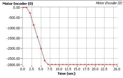
With the graph produced by our physics bot, we determined the degrees the motor rotated, 2800 degrees, and the amount of time, 7.4 seconds. We divided 2800 by 360, the total degrees of a circle, and got 7.77, which is the total number of rotations. We then multiplied this by 7.065, which is the circumfrance of the wheel. We received 4.6, which means the robot went 4.6 ft./second. The team that we went up against gave us a speed of 5.2 ft./second. We added these two speeds together. We then took the length of the black line, 10 feet and diveded it by 9.8 ft, which is the sum of the two speeds. We got an answer of 1.02 seconds, which means that the two robots will meet 1.02 seconds after we started both robots.
Reflection Guide
The assignment is to have two robots go head-to-head and figure out when they will meet on a 10 foot line.
Before I begin, I needed to figure out the math involved to find the point at which the robots will meet. I studied the formulas Mr. Croke put on his website and follwed them throughout the assignment.
I first built a simple robot with a light sensor, which I have done in the past. I then put to touch sensors in the front for when the robots meet. I then put a sound sensor on the top of the bot, completing the robot. Creating the program was the most difficult task. We assumed that the light sensor and touch sensors would work perfectly together, but it did not turn out the way we expected. Only the light sensor or the touch sensors worked alone, both could not work together. This happens probably because the jumps will only work with the task that it surrounds. I split the light sensor task and the touch sensor task and put jumps only on the light sensor task. Unfortunately this could work and we had to change our program to the one seen below.
Our robot, which was at power level 3, went against another robot at power level 5. We let the robots go at the same time and had the touch sensors stop the motors once the two robots met in the middle. We uploaded the graph that was produced by motor logging and it gave us the graph seen below. We figured out that the motors rotated 2800 degrees in about 7.4 seconds. Given the circumfrance of the wheel and the amount of rotations, we figured out the speed of the robot, 4.6 ft/second. We added this to the other robots speed, which was 5.2 ft/second. Then we took the length of the black line, 10 feet, and divided it by 9.8. We got 1.02 seconds which means that the robots will meet in 1.02 seconds after start.
We first started with our initial design which was a robot that follows the black line once it hears a loud noise and stops when the touch sensor is pressed. We figured out it was not possible to have the touch sensor and the light sensor work at the same time. Mr. Croke suggested that we should change our program and just have the robot go forward instead of following the black line. We took this advice and in the end it worked out.
I learned about the complexity of different sensors attached to the NXT at the same time. I also learned to calculate for when the two robots will meet using the formulas Mr. Croke provided for us.
If I could do the project again I would work more with the program to make a robot that follows the black line and uses the touch sensor to stop all at the same time.
Physics Bot Program Physics Bot Graph
Project 8
Battle Bot

Thjis is our battle bot project. The assignment is to make a robot that can go against another robot, flip it over, push it out of the boundaries, or disable it. Our bot is designed to flip other robots over by using the ramp as seen on the front of our robot. We made a small-to-large gear ratio so that the ramp can have more strength as it lifts up other robots. We already knew that we were going to have to do something more inovative for our robot to win. Instead of having a simple program that runs on its own, we wanted to have full control of the bot. We made a controller using touch sensors to have control of the bot.
Each touch sensor operates a different part of the bot. The outer right touch sensor controls the right motor, the outer left motor controls the left motor, the inner left touch sensor makes the robot go in reverse, and the inner right toucher sensor activates the ramp that wil lift the other bots. From this project I learned much about complex programing, by using the touch sensors to control each motor we could do almost anything with the bot and not have to rely on a program that runs on its own. If I could do this project again I would try to perfect the ramp in front of our bot. It had problems staying together and in some instances was hard to lift up other robots.
Each touch sensor operates a different part of the bot. The outer right touch sensor controls the right motor, the outer left motor controls the left motor, the inner left touch sensor makes the robot go in reverse, and the inner right toucher sensor activates the ramp that wil lift the other bots. From this project I learned much about complex programing, by using the touch sensors to control each motor we could do almost anything with the bot and not have to rely on a program that runs on its own. If I could do this project again I would try to perfect the ramp in front of our bot. It had problems staying together and in some instances was hard to lift up other robots.